Au Group Electronics logo
Last Updated on: February/21/2023
for 1024x768 & higher screen resolution
Telephone:+1(774)929-7084
>System>GW4
Find other system products:

Au Pressure to J1939/J1708 Gateway (GW5)

Au Pressure to CAN/J1939 Gateway (GW5)

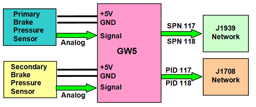
Au Gateway 5 (GW5) is a gateway device. It converts pressure signals from up to two pressure sensors to digital format of "Brake Primary Pressure " and "Brake Secondary Pressure" information onto J1939 and J1708/J1587 network. GW5 supports Bendix pressure sensor part # 5005758, 5008677.

Supported J1939 Parameters (SA: 23 and 33)

  • Brake Primary Pressure: 65274 (0x00FEFA) byte 2 SPN 117

  • Brake Secondary Pressure: 65274 (0x00FEFA) byte 2 SPN 118

Supported J1708 Parameters (MID: 140 and 249)

  • Brake Primary Pressure: PID 117

  • Brake Secondary Pressure: PID 118

GW5 function Block

Au GW5 function block

Features

  • Nominal Power Supply: Operating range: 12V DC nominal input, +14.2V DC recommended
  • Operating Electric Current: 65mA typical, 250mA max
  • Operating Temperature: -40°F to 158°F (-40°C to 70°C)
  • Compact size: 4-1/8" L X 1-3/4"W X 7/8"H
  • Enclosure Color: Black
  • Dual CAN Baud Rate: supports Two field configurable CAN baud rate: 250K and 500K
  • Audile warning and LED indicators
  • RS232 side DB9 female connector: for firmware boot-loading purpose
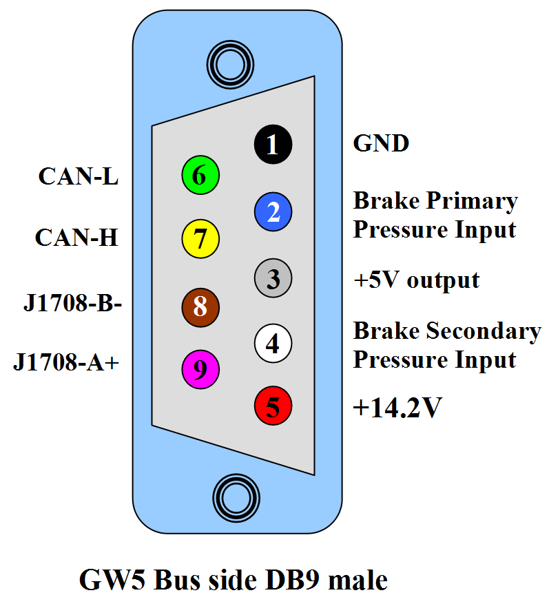
  • BUS side DB9 male connector: for power, J1939 network, J1708 network, pressure sensor signal inputs and output +5V to pressure sensors
pin-out on BUS side DB9 male connector

Hardware Connection

Au GW5 is a handheld gateway device. It can run independently without a computer. A typical topology of SAE J1939 network with GW5-PS-CAN is illustrated here:

typical topology of SAE J1939 network and J1708/J1587 network with GW5

On the RS232 side, Au Gateway 5 (GW5) can be connected to a computer through a USB to RS232 convert cable (part #: CBL-USB-01). Connection to PC is only used for firmware boot-loading purpose, computer is not necessary during general use.

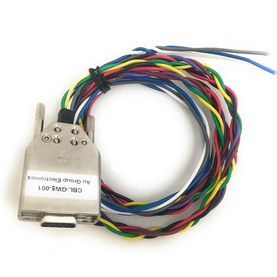
On the Bus side, a 9-wire pigtail cable (part #: CBL-GW5-001) can be used to connects GW5 to power supply, J1939 network, J1708 network, and up to two pressure sensors.

For testing purpose, an optional Digital Gauge Driver can be used to connect to the J1708 network and drive Primary pressure gauge and Secondary pressure gauge.

Note: All devices must use the same reference ground.

GW5 LED Settings and Status

Au GW5 equipped with 3 push buttons (Menu, Down, Up) and 9 LEDs (one of the LED is not in-use for GW5)
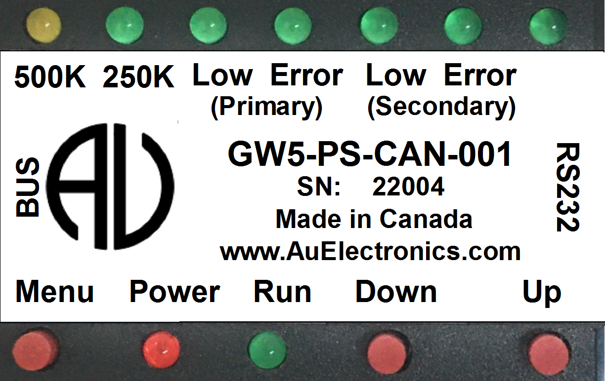
Push button and LED on GW5

When GW5 is powered up with +14.2V DC, Power LED will be constant on, Run LED will blink at 1 second interval. One of the CAN baud rate LED (250K/500K) will lit depends on the device CAN baud rate setting.

To switch CAN baud rate, press and hold both Menu and Down buttons at the same time until LED status change. In the following figure, the first LED (Yellow) lit up indicates GW5 device is setting at 500K CAN baud rate
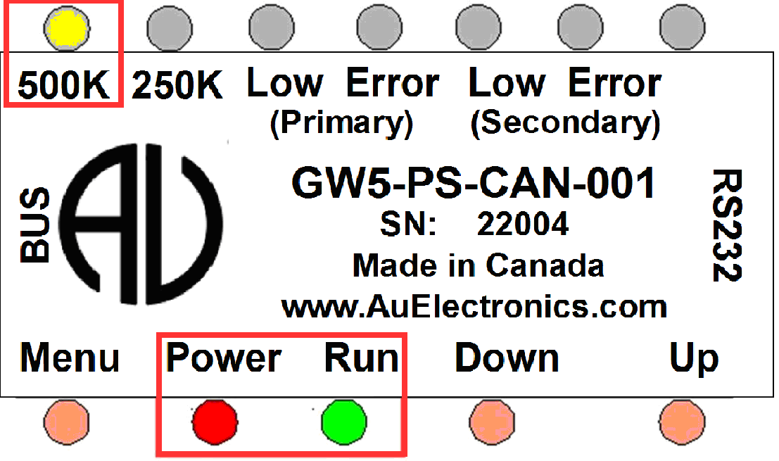
GW5 CAN baud rate is setting at 500K

And in this figure the second LED (Green) lit up indicates GW5 device is setting at 250K CAN baud rate
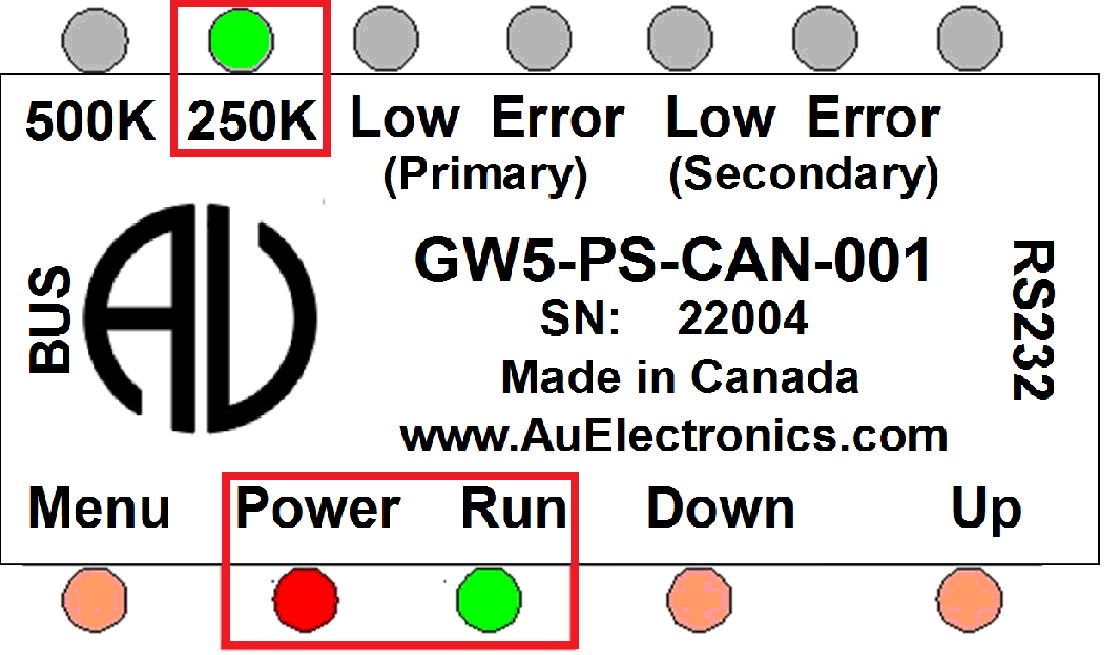
GW5 CAN baud rate is setting at 250K

Here is the summary of LED indicators on device status, and how to use push buttons to change device settings.

LED Device Status
Power Constant on. Device is powered up
Run Blink every 1s. Device runs normally
500K When the LED is on, Devices running at 500K CAN baud rate
250K When the LED is on, Devices running at 250K CAN baud rate
(Primary) Low When the LED is on, Primary brake Pressure is below 62 PSI
(Primary) Error When the LED is on, Primary brake Pressure Sensor not connected or malfunction
(Secondary) Low When the LED is on, Secondary brake Pressure is below 60 PSI
(Secondary) Error When the LED is on, Secondary brake Pressure Sensor not connected or malfunction

Note: the 500K and 250K LED are mutual exclusive, only one LED will be on at a time. They cannot be both on, nor both off.

GW5 Push Buttons

Push Button Operation Device Settings
Press Down button Decrease backlight
Press Up button Increase backlight
Press and hold both Menu and Down button Switch between 250K / 500K CAN baud rate
Press and hold bothUp and Down button Silent the buzzer, the buzzer can only be turn off when warning is on, it will be automatically turned on at each power reset.

Buzzer Warning

GW5 has both audible and LED warning indication. If GW5 detects one of the following situation, a beeping will sound out at 1 second interval:

  • GW5 is not connected to primary pressure sensor or primary pressure sensor malfunction
  • Primary brake pressure is lower than 62 PSI
  • GW5 is not connected to Secondary pressure sensor or Secondary pressure sensor malfunction
  • Secondary brake pressure is lower than 62 PSI

To silent the buzzer, press and hold both Up and Down button. The buzzer can only be turn off when warning is on, it will be automatically turned on at each power reset.

View or donwload the printable version of GW5 User Manual

GW5 Demonstration

Following video demostrated that Au GW5 receives anolog pressure signals from pressure sensors, then convert them into to digital format of "Brake Primary Pressure " and "Brake Secondary Pressure" information onto J1939 and J1708/J1587 network.

GW5 and Optional Cables

GW5-PS-CAN
GW5: Au Pressure to CAN/J1939 Gateway
Part #:GW5-PS-CAN       Price: $360 USD
GW5 User Manual
USB to RS232 Converter Cable
Part #: CBL-USB-232        Price: $15.99 USD
9-wire Gateway5 Cable (pigtail)
9-wire Gateway1 Cable (pigtail) for DB9 male connector, can be used to connect Au GW1 device to J1939 CAN bus or J1708 bus, or OBD2-CAN bus, tachometer, and speedometer. 2 feet length
Part #: CBL-GW5-001       Price: $39.99 USD
CBL-GW5-001 Datasheet
PWR-912V-CP

Wall Mount AC/DC Power Supply - Positive Center
Part#: PWR-912V-CP      Price: $14.99 (USD)