dsPIC30F CAN Bootloader Evaluation Kit User Manual
(Rev. B, June-2008)
Note:
1. This dsPIC30F CAN (Controller Area Network) Bootloader Evaluation Kit is for Au Group Electronics dsPIC-CAN bootloader evaluation purpose only, it may be used for lab test, but it can not replace real field test.
2. The actual device/network cables in each evaluation kit might be different than the picture shown in this document. Au Group Electronics reserve the right to change any devices/cables accordingly without further notice.
Au Group Electronics dsPIC30F CAN-Bootloader Evaluation-Kit (Part#: EVK-XXXXX-CAN-BLD-xxxK) includes all necessary hardware and software to evaluate the Au Group Electronics developed dsPIC30F CAN bootloader (Part#: BLS-CAN-XXX).
This document will show you how to set up a CAN network step by step, then test Au Group Electronics developed dsPIC30F CAN bootloader by using this CAN network. The following document gives an example for a 500K CAN test network and an evaluation board with dsPIC30F6012A chip.
Hardware List
Device Name |
Part # |
Function |
SAE-J1939 Simulator |
SIM-J1939-006 |
J1939 Signal source (tuned up for 500K bps) |
Bootloader Converter Box: RS232 to CAN |
BLC-CAN |
Convert RS232 signal to CAN signal (with 500K bps CAN firmware) |
SAE-J1939 Message Center |
MCSJ1939-001 |
Display J1939 Signal (with 500K bps CAN firmware) |
dsPIC30F6012A CAN Bootloader Demo Board |
EVK-6012A-CAN-BLD-500K |
Demonstrate CAN Bootloading process with dsPIC30F6012A processor |
Connectors (0F, 1F, 1M, 2F, 2M, 3F, 3M, 4M) |
N.A |
Node connection (CAN-H, CAN-L, PWR, GND) 1F mate with 1M, 2F mate with 2M, 3F mate with 3M, 1 spare male connector (4M), 1 spare female connector (0F) |
Power Supply |
PWR-912V-CP |
Provide +12V 500mA power supply to all devices |
Cables |
N.A |
Connect all CAN nodes |
PCs with RS232 serial ports or USB port with USB/RS232 converter (Not provided) |
N.A |
For CAN signal demonstration and CAN bootloading |
Software List
-
Au Group Electronics PIC Bootloader Evaluation Edition (Non-encryption)
-
Au Group Electronics SAE-J1939 Simulator Application Software
-
Au Group Electronics SAE-J1939 Message Center System (MCS) Application Software
-
"LedBlink.hex" file, which will blink the two rows of LEDs on the demo board.
-
"LedRotate.hex" file, which will keep the two rows of LEDs "running" on the demo board.
Document List
-
Au Group Electronics User Manual for Bootloader Converter Box: RS232 to CAN
-
Au Group Electronics SAE-J1939 Simulator User Manual
-
Au Group Electronics SAE-J1939 Simulator Remote Terminal Installation Guide
-
Au Group Electronics SAE-J1939 Simulator License Management Toolset
-
Au Group Electronics SAE-J1939 Message Center System User Manual
-
Au Group Electronics dsPIC30F CAN Bootloader User Manual
Step by step instruction on Setup a CAN Network
-
Install all provided software on PCs (refer to relative user manuals for software installation).
-
Connect hardware devices using provided cables and mating the male/female connectors according to following list:
-
Connect BLC-CAN device to one of DB9 connector
-
Connect SAE-J1939 MCS device to one of DB9 connector
-
1F mating with 1M
-
2F mating with 2M
-
3F mating with 3M
-
0F and 4M not in use
-
Use RS232 extension cables to connect SAE-J1939 MCS, BLC-CAN, and SAE-J1939 Simulator to PCs. The network is illustrated in figure 1.
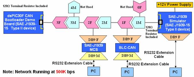
Figure 1 CAN Network for dsPIC30F CAN-Bootloader evaluation
-
Plug +12V power supply to SAE-J1939 Simulator, all devices in the network will be powered up and running. The network will be looking like below, as shown in figure 2, the red line highlighted the backbone of CAN network.

Figure 2 CAN Bootloader demonstrating network with Au Group Electronics developed devices
Note: The actual device/network cables in each evaluation kit might be different than the picture shown in this document. Au Group Electronics reserve the right to change any devices/cables accordingly without further notice.
The Au Group Electronics developed "LedBlink.hex" file and the dsPIC30F CAN bootloader hex file are pre-loaded to the dsPIC30F CAN Bootloader Demo Board, the Power LED is constant on when powered up, and the two rows of LEDs (4 LEDs on each row) are blinking at the interval frequency of about 1 second.
Next paragraph will show you how to load a new application hex file: "LedRotate.hex" to the Demo Board by using the CAN bootloading technology step by step. This will change the two rows of LEDs from "Blinking" status to "Rotating" status without taking the enclosure apart.
How to Step by Step Bootload a hex file through the CAN Network
There are two methods to force the demo board entering bootloader mode:
Method 1: use the "Reset PIC" button on "Au PIC Bootloader" software from the PC while the demo board is running.
Method 2: flip the toggle switch (it is attached on the demo board, figure 2) to connect +12V supply to Pin 7 on demo board, unplug the power supply on the J1939 simulator, and then plug it back.
(Note: Make sure the toggle switch is flipped back after bootloading, otherwise it will enter bootloader mode for 10 seconds at every power up thereafter.)
The following steps used Method 1 to force demo board entering bootloading mode, user can also try method 2 at step 5.
-
On PC with Au PIC bootloader software installed, double click "Au PIC Bootloader V1.00B" shortcut, as shown in figure 3.

Figure 3
-
Click "Load File" button in "Au PIC Bootloader By Au Electronics 1.00B (Eval Edition) " window, as shown in figure 4,
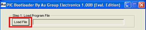
Figure 4
-
Select "LedRotate" hex file, then click "Open", as shown in figure 5
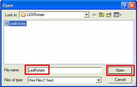
Figure 5
-
File name "LedRotate.hex" display, then select RS232 serial port, set speed at 11520 (figure 6).
-
Click "Reset PIC" button (figure 6) will trigger the dsPIC30F CAN bootloader demo board enter bootloading mode: bootloader LED (D12, as shown in figure 7) on demo board blinks, Power LED (D11, as shown in figure 7) constant on, all other LEDs are off. Method 2 can also be used to force demo board entering bootloading mode.
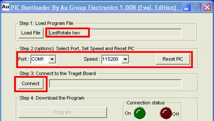
Figure 6
-
Within 10 seconds, click "Connect" button (figure 6).
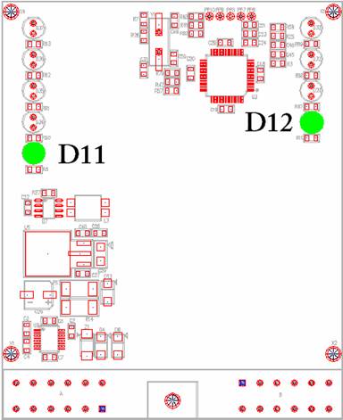
Figure 7
-
The connection status ON indicator on computer screen will turn Green. Also the Bootloader LED (D12) on the demo board will be constant ON, click "Program" button ( figure 8)
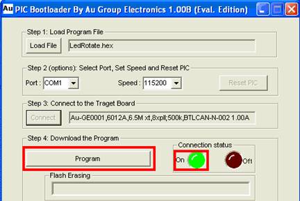
Figure 8
-
Flash Erasing and Programming progress bar will be moving as bootloading proceed, a long beeping on PC indicates bootloading accomplished, click "Exit" to close the program, as shown in figure 9.
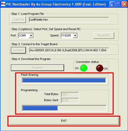
Figure 9
On demo board, Bootloader LED (D12) will now be off, and 8 LEDs will be rotating counter-clockwise all the time thereafter.
Above steps changed the two rows of LEDs from a "Blinking" status to a "Rotating" status in-field with the state of art CAN bootloading technology.
Repeat above 1 to 8 steps and select the "LedBlink.hex" file at step 3, it will change the two rows of LED from "Rotating" status back to "Blinking" status. The 2 rows of LEDs on the demo board will start blinking at 1 second interval again thereafter.
Monitoring CAN Network while Bootloading via CAN bus
The Au Group Electronics SAE-J1939 simulator and the Au Group Electronics SAE-J1939 Message Center will be always on and talking to each other over CAN network whenever the power is on. Their data stream creates a relative "noise" network environment for CAN bootloader test. However, the bootloading data should always manage to go through the CAN network without interfering with non-bootloading data and update the flash on the target board successfully.
PC and application software are not necessary to make those network nodes (J1939 simulator and J1939 Message center) fully function, however the PC application software does provide good human-machine interface to show J1939 data flow on CAN network in a real time basis.
On the PC with Au Group Electronics J1939 Simulator Remote Terminal installed, double click "Au J1939 Simulator Remote Terminal" shortcut (figure 10-a) to open up "Au J1939 Simulator Remote Terminal Ver. 1.00A" window, check Dynamic (figure 12), it will make the J1939 simulator generate dynamic data automatically, and broadcast those data to CAN network.
On the PC with Au J1939 Message Center System installed, double click "J1939MessageCenter" shortcut (figure 10-b) to open up "Au J1939 Message Center V1.00A" window (figure 11). It shows an instrument panel with 6 analog displays, 17 digital displays, and 8 message/warning lamps. It vividly demonstrates most of the received SAE-J1939 data on the CAN network.


Figure 10-a Figure 10-b
The following figures just give a rough idea what they looked like, for detail information of using those tools, please refer to their own user manuals.
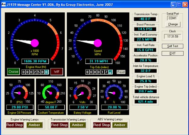
Figure 11
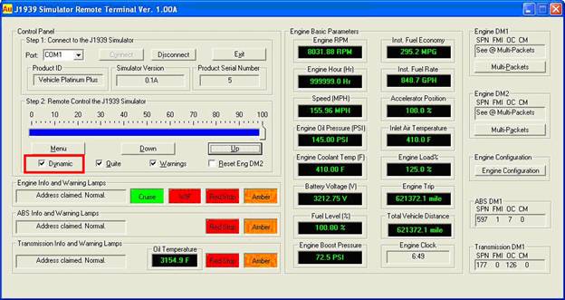
Figure 12