LED RUNNER
(PRG0802 Application Note Rev. A)
By Au Groups
Jan. 2008

This document is one of the application notes for Au Group Electronics 8-pin integrated circuit chip: LED Runner (Part#: PRG0802P and PRG0802SN).
Features
-
Low power CMOS design
-
Wide power supply range from 3.0 to 5.5 volt.
-
Low power mode to saves batteries
-
Single push-button to activate LEDs running
-
Direct drive for high current outputs
-
No expensive external timing components required
Applications
Absolute Maximum Ratings
-
Storage Temperature: -65°C to +150°C
-
Ambient Temperature: -40°C to +85°C
-
Voltage: 0 to +5.5V
-
Max Pin Sink/Source Current: 25mA
Note: Stresses beyond parameters listed here might damage the device.
Typical Operation Characteristics
-
Supply Voltage: 3.0 to 5.5V
-
Power on voltage rise rate: >0.05V/ms
-
Average supply current when LEDs are running: 2mA (3V) to 6.5mA (5V)
-
Average sleep current: 80 uA (3V) to 250 uA (5V) with recommend resistors in this application note
-
Typical R1 resistance: 47K ohm
-
Typical R2 resistance: 0 to 300 ohm
-
Typical LED rotate frequency: 2 to 3 Hz
-
Typical LED driver output pulse duration: 20 ms
-
Typical LED running time with every single switch input pulse: 15-20 seconds
Description
The Au Group Electronics PRG0802 is an 8-pin 8-bit flash microcontroller with integrated program. The PRG0802 is a fun circuit for driving up to five LEDs. One push button input will initiate about 15 to 20 seconds of LED “running” activity. Its low current consumption feature makes it also a good candidate for battery-powered toys.
All of the control logic required for circuit operation is contained within the PRG0802 8-pin integrated circuit. Normally only batteries, 5 LEDs, 1 push button switch, and 2 resistors are needed for a completed LED runner circuit.
The PRG0802 drives each LED output in a sequential fashion at approximately 2~3 Hz frequency. With one LED output at a time the current will be maintain at the lowest level.
Pin Descriptions:
The PRG0802 are available in either 8-lead PDIP package (300mil) or 8-lead SOIC surface mount package (3.90mm). Table 1 list the Au Group Electronics part numbers for both packages.
Table 1 Available package and part number of PRG0802 at Au Group Electronics
Part number |
Package |
PRG0802P |
8-lead 300mil plastic Dual In-Line Package (PDIP) |
PRG0802SN |
8-lead 3.90mm body Plastic Small Outlines-Narrow (SN) SOIC |
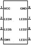
Both PDIP and SOIC package of PRG0802 share the same pin function, it is illustrated in figure 1 and described in table 2.

Figure 1 Pin Function of PRG0802 (for both PDIP and SOIC package)
Table 2 Pin Descriptions of PRG0802
| Pin # |
Pin Name |
Description |
1 |
Vcc |
Positive side of power supply |
2 |
LED4 |
LED driver 4 |
3 |
LED5 |
LED driver 5 |
4 |
SW1 |
Switch input 1, Can be connected with a tact switch/push button, its input will be used to trigger one LED running event |
5 |
LED1 |
LED driver 1 |
6 |
LED2 |
LED driver 2 |
7 |
LED3 |
LED driver 3 |
8 |
GND |
Ground, Negative side of power supply |
Pin LED1 to Pin LED5 are five independent LED drivers. The 5 LEDs can be lit by the following 2 ways.
When initially power on,
5 LED lights rotate alternatively from 1 to 5. After LED 5 is on, the next one will be LED 1 again. The 5 LEDs will running in the frequency of 2 to 3 Hz for 15 to 20 seconds, and then enter the low power mode (all LEDs will be off).
During the low power mode,
Press push button SW1 will wake up PRG0802 and start another 15-20 seconds of LED running event.
Each output pin is capable of providing maximum current of 25 mA.
Example:
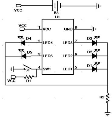
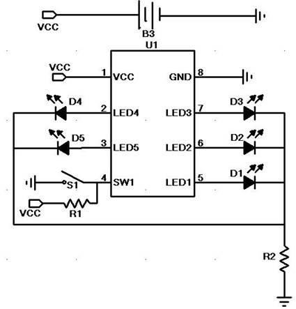
Figure 2 illustrates a typical connection of a LED Runner circuit system. Battery group B3 could be consisted of 2 to 3 AA type batteries connected in serial. Resistance of R1 should typically be 470K ohm, and R2 should typically be 0 to 300 Ohm. D1 to D5 are LEDs with typical forward voltage of 1.8 to 2.5V. S1 is a push button.
At power on, LEDs keep running for 15-20 second as a self test, then the PRG0802 enters a low power mode.
At low power mode, pressing push button SW1 once will initiate a sequence of LED running for another 15-20 seconds, then it return back to low power mode again. This control strategy is used to detect the switch/button input events and conserve maximum energy for battery applications.

Figure 2 Typical circuit connection of a LED Runner system
============================ End ============================


