Last Updated on: March/20/2018 |
for 1024x768 & higher screen resolution |
Telephone:+1(774)929-7084 |
| >Downloads>CVT485 |
RS485 Converter User ManualBy Au Groups (Rev. C, March-2009) Thank you for choosing Au Group Electronics RS485 Converter (Part #: CVT485, CVT485E, CVT485-NE, and CVT485E-NE)! The RS485 Converter is a handheld device typically used for converting RS485/SAE J1708 signal (two-wire operation balanced half-duplex) to a RS232 signal (two-channel) and vice verse. An external +12V power supply is required. It has a DB-9 female RS-232C connector and a DB-9 male/female connector on the RS485 bus side. The DB-9 male-connector and its cable on the RS485 side is the most popular choice. Major Features:
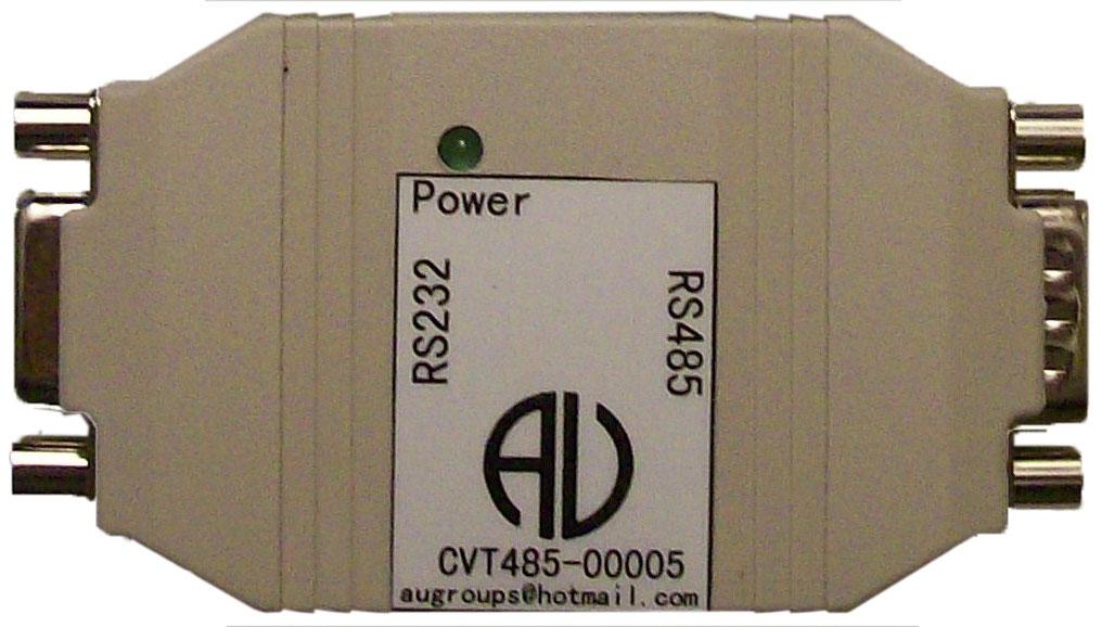
Description: A RS485 converter is illustrated in figure 1.
There is 1 LED power indicator on top view, and it will be on when the device is connected to +12V power supply. RS232 connector pin out is shown in figure 2. RS485/SAE J1708 female/male connectors are shown in figure 3 and Table 1.
Figure 2 RS232 Interface A-Male (most popular) B-Female Figure 3 RS485/SAE J1708 interface For male RS485/SAE J1708 interface (most popular), position 1 is ground (GND), position 5 is +12V power supply, position 8 is Data B (-) / J1708-, position 9 is Data A (+)/J1708+, and all other positions are not connected (NC). For female RS485/SAE J1708 interface, position 1 is +12V power supply, position 5 is ground (GND), position 6 is Data A (+)/J1708+, and position 7 is Data B (-) / J1708-, all other positions are not connected (NC).
Table 1 RS485/SAE J1708 Female/Male Connector Pin Out
Step by Step operation:
Limited Life Time Warranty: AU Group Electronics provides limited life time warranty to this product under normal use, in accordance with the specification and warning, for as long as you own this product. This warranty extends only to the original purchaser of the product, and is not transferable. To exercise your rights under this warranty, you must provide proof of purchase in the form of an original sales receipt/shipping memo that shows the product name and the date of purchase. Any non-authorized modification to hardware will violate this warranty. Shipping cost for any return material will be carried by purchaser.
|


